The output for each section of the mixer may be separated to provide separate outputs to connect to the separate inputs of computer soundcards.
Power requirements for the mixer is either a plugpack 9V to 24V or a 9V transistor battery.
The mixer is really handy for DI'ing guitars and basses into soundcards or other mixers and making use of channels on mixes that do not have mike in's, it comes in handy for one or two guitarists that want to sing and play through one guitar amplifier as well.
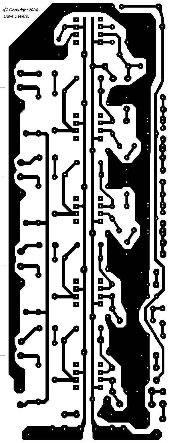
The printed circuit board will not be exactly the same as the one in the pictures, it will be a bit better it has pots mounted on the broad in the same way as they are mounted on the board for the compressor. A second board design with a slightly different arrangement of the plots to suit lower impedances and separate direct outputs for soundcards will be included. The difference between the two arrangements in respect to specifications is unnoticeable. The components on the first board may be rearranged and tracks broken to form the circuit provided by the second board or the board that best suits your application can be chosen. If enough interest is expressed in this project there maybe a ready-made PCB board available through this website.


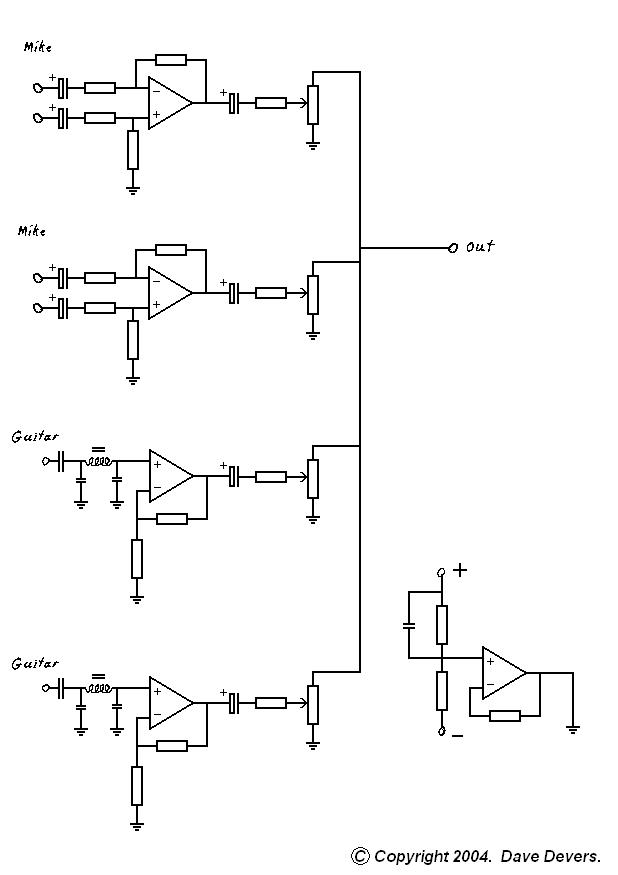
Above is the circuit diagrams and PCB's for the mixer, Including component values and layout.
The output for each section of the mixer may be separated to provide separate outputs to connect to the separate inputs of computer soundcards.
Power requirements for the mixer is either a plugpack 9V to 24V or a 9V transistor battery. A maximum of 12V is advised for use with sound cards.
The bias voltage for all of the opamps is derived from a voltage divider consisting of two 10K resistors that provide a mid voltage point, this voltage is then amplified through an opamp to lower noise introduced by the resistors, the output of this opamp is the bias input for the other opamps. If you are going to be using the same supply voltage all of the time then noise can be lowered a little more by replacing one of the resistors in the voltage divider with a zener diode, chose a zener that is close to half the supply voltage.
The mixer is really handy for DI'ing guitars and basses into soundcards or other mixers and making use of channels on mixes that do not have mike in's, it comes in handy for one or two guitarists that want to sing and play through one guitar amplifier as well.
Two printed circuit boards are described, the first is more suited for the input of a guitar amp, the second is more suited for the input of soundcards. On the second board the outputs are connected together. To implement separate outputs break the track connecting the outputs and replace the 10k output resistors with 1k resistors.
The PCB board diagrams are 200% photocopy them onto a transparency at 50% they work better this way! First make 50% copies on plane paper to check the size is going to be right. They can be printed directly to transparencies with the right ink and printers, many copying shops can do this for you.
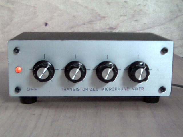
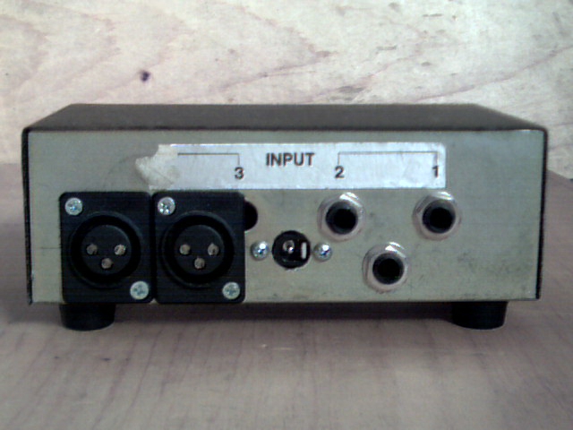
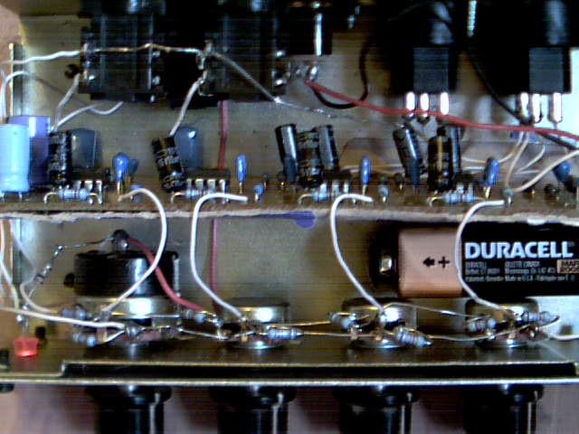
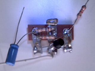
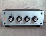
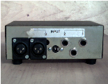
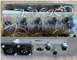
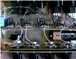
Originally this mixer was one that I brought many many years ago, the original circuit consisted of 1 transistor, 7 resistors, 2 capacitors and 4 potentiometers, it was a bit noisy and had a gain close to unity. It had been sitting there for many years until a small mixer was needed, the mixer as it was, was just not good enough how it was. So a new circuit and PCB board was designed and placed in the original chassis, a couple of balanced canon sockets were installed on the back, the original pots were too high in value so a couple of resistors were parallel across each one of them, this can be seen from the photo. Before all this it was a transistorised microphone mixer, what a beauty! Now it is a integrated circuit guitar microphone mixer.
And here She Is or should I say was, well you can see there is